|
|
 
| |
This HP describes advanced drawing editing functions equivalent to 2D-CAD
supported by PloView, PloComp. You can load and edit various graphic files
(below) and save them in various graphic files.
HP-GL, HP-GL/2, HP RTL, PDF, DXF, DWG, GERBER, NC-Drill, IGES, SXF, TIFF,
JPEG, BITMAP, EMF, PCX, FPX, PNG, GIF |
|
|
|
 Index Index |
|
Outline
File
Set
Undo, Redo
Insert
* Polyline(Line,Arrow,Cloud mark,B-Spline,Dotted line,Dashed line,Surface)
* Line
* Horizontal/Vertical/Slanting line
* Circle, Arc
* Regular Polygon
* Free Curve
* Offset Line
* Rectangle,Long Circle
* Text
* Bitmap
* Macro
* Dimension
Select
Select all comment
Display comment property
Change comment property
Delete
Move
Rotate, Scale Up/Down
Divide/Delete/Move/RouteChange Polyline section
Shape Change of Polyline Vertex
Delete line in selected area boundary
Trim Line
Connect Line
Macro-izing
Macro breakUp
Connect window with surface
Copy, Cut, Paste
Convert Connect Line to Comment
Convert ViewData to Comment
Display
Setup of pen
Text font
Request
Output
Contact us
|
|
|
|
Outline
|
|
* Usage
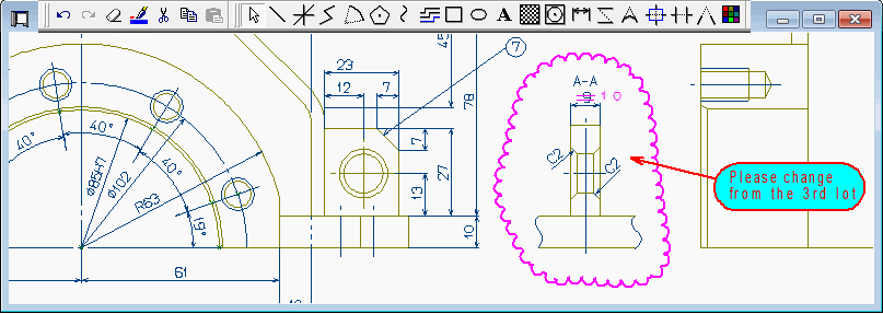
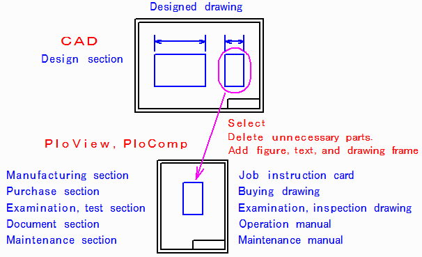
Drawing released from design department turns into another drawing
variously processed by downstream sector. For example, it becomes job instruction
card at manufacturing department, examination and inspection drawing at
quality control department, operation manual at document section, maintenance
manual at maintenance division, etc. If it can obtain instead of drawing
of paper from design department by electronic data of HP-GL, PDF, DXF,
DWG, GERBER, NC-Drill, IGES and SXF, it is easily processible into another
drawing by PloView and PloComp.
Use of drawing editing function
* Function
PloView and PloComp have about the same powerful input editing function
as 2D-CAD, can read various view files (HP-GL, PDF, DXF, DWG, GERBER, NC-Drill,
IGES, SXF, image), and can edit them. And, new drawing creation enables.
This page introduces the drawing editing function.
< Retun to Index > |
| |
|
|
File
|
|
File function
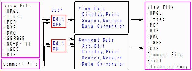
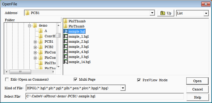
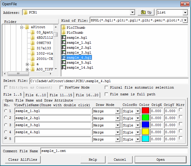
* Open.
(1) New comment file creation
(2) Open view file by edit OFF
Use it, when seeing view file, and adding comment.
View file cannot be edited.
Comment file linked to view file is newly created, or if there exists
linked comment file, it will open automatically, and it can edit.
View file and comment file overlap and are displayed.
(3) Open view file by edit ON
Use it, when editing view file.
View file is converted into comment data and can edit.
View file does not display.
(4) Open comment file (it is not related to edits ON/OFF).
Use it, when editing comment file.
* Save
Edited comment data can be saved.
And, comment data is converted into view file and can be saved.
Comment file is file which can read and write only PloView and PloComp.
- How to offer comment file name (example)
ABC.hgl View file (in the case of HP-GL file)
ABC.cmt Comment file linked to view file
ABC_hgl.cmt Comment file which converted view file
* PloView original function
Although PloView opens only one view file simultaneously, it corresponds
to multi-page.
When view file is opened by edit ON, page number (1-20) of view file will link to layer number of comment file, and will be converted into comment file.
* PloComp original function
PloComp can open up to 20 files of view file at the same time.
When view file is opened by edit ON, file number (1-20) of view file will link to layer number of comment file, and will be converted into comment file.
< Retun to Index >
|
|
|
|
Set
|
|
* Set attribute values for each figure type when each figure is entered.
* Set the graphic type to be selected, the polygonal line selection method,
and the selection area.
* Set display layer.
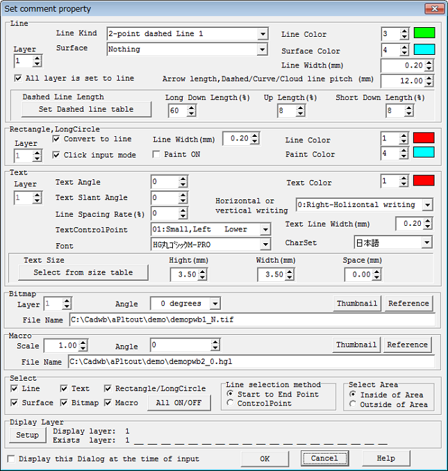
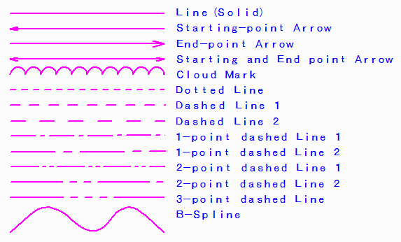
*Line
- Line Kind
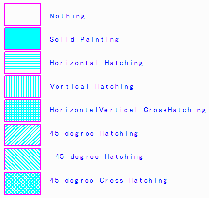
- Surface
* Rectangle, Long circle
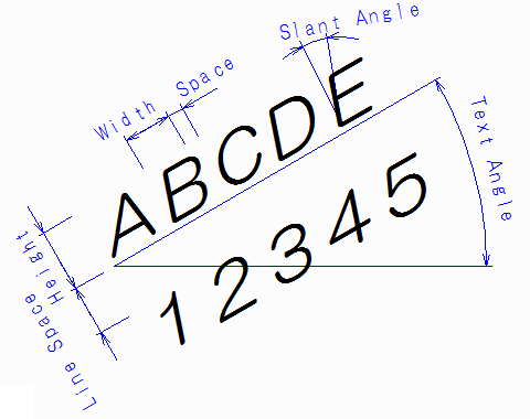
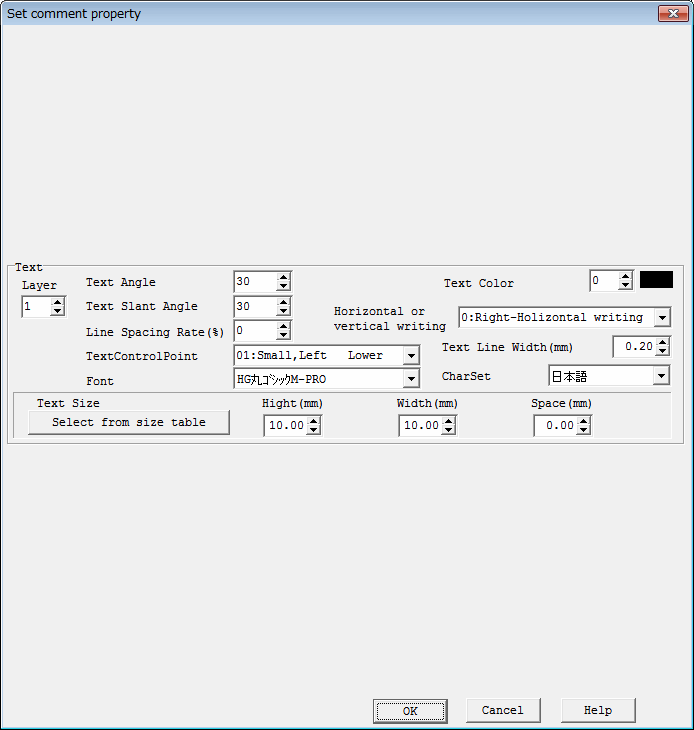
* Text
- Text has many properties.
Please refer to the figure at the bottom.
Text Control point
Select Text control point (X positions of the following figure)
from 1-9, 11-19 which are shown below.
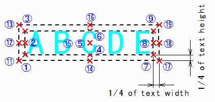
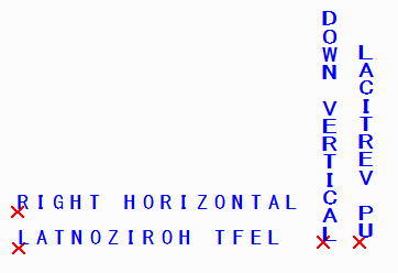
Horizontal or vertical writing
In each case, Text Angle is 0 degree and TextControlPoint
X is (1).
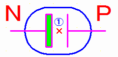
* Bitmap
- Bitmap files which can be inputted are TIFF, JPEG, Bitmap,
PCX, FPX, GIF, and PNG format.
In addition, file name will be set to "*n" (n is management number) when it converts into comment file from view file containing Bitmap.
External file does not exist.
- Angles is 0, 90, 180, and 270 degree.
- Following figure (1) is control point.
* Macro
- Macro also be called it complex graphic and consists of plural above
polylines, rectangle, long circle, text, bitmap, and macro.
- Macro file can specify HP-GL, PDF, DXF, DWG, GERBER, NC-drill, IGES,
SXF, EMF, TIFF, JPEG, Bitmap, PCX, FPX, GIF, PNG, and comment file.
In addition, Macro can be created by Macro-ized command except reading from file, file name is "*n" (n is management number), and external file does not exist.
- Any angle and any scale can be specified.
As for the following figure, (1) shows constituting points in example
which consists of polyline, Long circle, and text.
* Layer
There exists layer to 1-20.
Layer which inputs figure, and layer to display can be set up.
Various drawing can be made from changing setup of ON/OFF of display
layer.
When PloView, page number links to layer number.
When page is changed in the case of multi-page ON, input layer and
display layer will change to page number automatically.
In the case of multi-page OFF, all the layers overlap and are displayed.
It is necessary to change input layer by property set.
When PloComp, file number links to layer number.
By "Displays in arranges", when Window is changed, input
layer and display layer will change to Window number automatically.
When "Displays in piles", all the layers overlap and are displayed.
It is necessary to change input layer by property set.
* Display this Dialog at the time of input
When this check is ON and comment will be inputted, since this dialog
is displayed, it can input, after setting property.
It is convenient when the property of comment to input changes each time.
This dialog will not be displayed when this check is OFF, and inputting
comment.
In order to change input comment property, before inputting comment,
it is necessary to select "Set comment property" menu, to display
this dialog, and to set.
It is convenient when the property of comment to input is the same each time.
< Retun to Index >
|
|
|
| |
Undo, Redo |
| |
* You can undo input edit operation for the comment that you have done
before. You can undo max of 100 data in the recently manipulated comment.
* When you undo the comment, you can redo one step at a time again.
< Retun to Index > |
| |
|
|
Insert Polyline
|
|
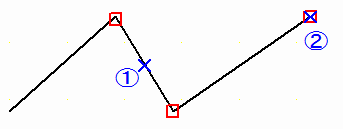
Inputs Polyline (Line, Line with arrow, Cloud mark, B-Spline, Dotted line, Dashed line, Chained line) set up by "Set comment property".
* Simple polyline
Carry out mouse left-click at order of (1) - (4), and press Enter key.
It inputted by line ( the upper figure ), B-Spline ( middle
figure ), and cloud mark ( lower figure ).
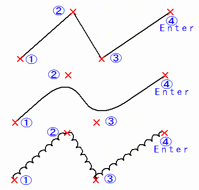
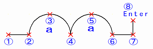
* Polyline containing arc
Simple polyline and polyline which combined line and arc can be inputted.
Click (1)(2) with left mouse, press "a" key, click (3)(4)
with left mouse, press "a" key, click (5) - (8) with left mouse,
and, finally press Enter key.
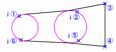
* Polyline which tangents arc
Polyline which tangents circle and arc which have already been inputted
can be inputted.
Inputs polyline which tangents two circles.
"j" key, left mouse click (1), "j" key, left
mouse click (2)(3)(4), "j" key, left mouse click (5), "j"
key, left mouse click (6), Enter key.
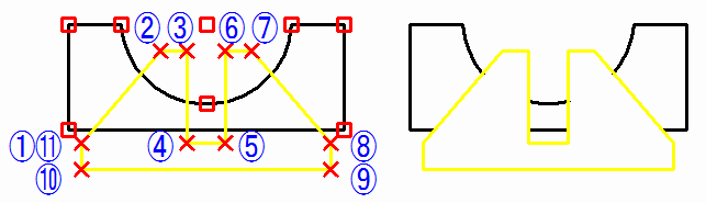
* Surface
Specify the surface attribute(Solid painting, various hatching) and input
the polyline.
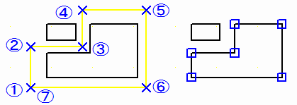
You can input surfaces by inputting closed polylines, as shown in the left
figure below (1), (2), (3), and (4).
To connect surfaces and specify windows, proceed as follows.
As shown in the figure on the right below, if you select four surfaces, right-click with the mouse and select the "Connect window with surface of comment" menu, the four surfaces will be connected and painting will be turned on/off.
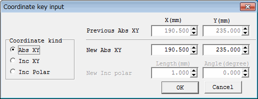
* Insert Coordinates at Key
Instead of left mouse click, when press "x" key, "Coordinate
key input" dialog appears, coordinates can be inputted numerically.
Coordinates can select and input absolute XY coordinates, relative XY coordinates, and relative polar coordinate.
Relative XY coordinates and relative polar coordinate are relative
values from coordinates inputted before one.
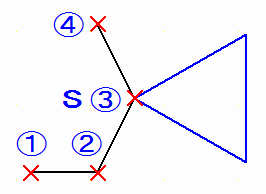
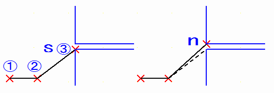
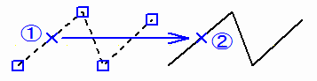
* Insert Same Point
Inputs into the same coordinates as constituting points of inputted
figure already.
Inputs polyline passing through vertex of triangle of inputted right-hand
side already.
Left mouse click (1)(2), "s" key, (3)(4) click.
* Next Same Point
When figures are crowded, if you enter the same point, you may recognize
another nearby figure.
When figure is crowded, nearby, another figure may be recognized
to carry out the same point input. Then, just after the same point input
command, press "n" key, then recognizes nearby another figure.
Figure with the another neighborhood can be recognized by repeating the
same operation. When nearby figure is not exists, message "Data is
not found !" comes out.
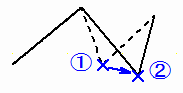
Figure below is expanded figure.
Two blue polylines are already included.
Input black line by the next operation.
Left mouse click (1)(2), "s" key, left mouse click (3)
(vertex of lower blue line)
Furthermore, when "n" key is pressed, it will move to vertex of blue line above nearby.
* Insert-Grid ON/OFF
While input, "g" key is pressed, input grid can be turned
ON/OFF.
When input grid is ON, it is come by off, and it is set to ON at the time of OFF.
< Retun to Index >
|
|
|
|
Insert Line |
|
Straight line (Line, Line with arrow, Cloud mark, B-Spline, Dotted
line, Dashed line, Chained line) set up by "Set comment property"
is inputted.
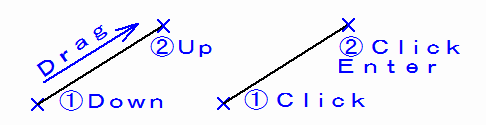
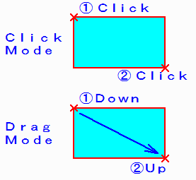
- Two kinds of input methods
The left figure shows method to drag and input.
The right figure shows method to click and input.
* "Insert Coodinates at Key","Insert Same Point","Next
Same Point","Insert-Grid ON/OFF"
When clicking and inputting, the same function as "Insert Polyline"
can be used.
< Retun to Index >
|
|
|
| |
Insert Horizontal/Vertical/Slanting line |
| |
Input horizontal line, vertical line, or slanting line by the contents
of line set up by line of "Set Property".
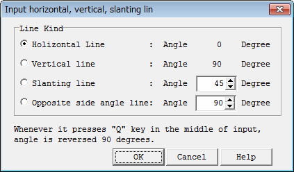
* Horizontal line is drawn at zero angle, and vertical line is drawn at
90 angles, and slanting line is drawn at specified angle.
* Opposite side angle line is drawn at angle which added specified angle
to recognized line angle (it is angle which is straight line in the case
of straight line and angle of the starting point to end point in case of
arc).
* "Insert Coodinates at Key","Insert Same Point","Next
Same Point","Insert-Grid ON/OFF"
The same function as "Insert Polyline" can be used.
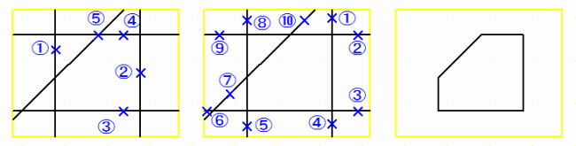
Example of use is shown below.
Left figure:
Input vertical line of (1)(2).
Input horizontal line of (3)(4).
Input slanting line of (5).
Middle drawing:
Click in order of (1)(2), (3)(4), (5)(6), (7)(8), and (9)(10) by
line connection command.
Right figure:
It is figure finally made.
Example of opposite side angle line
The following figure is example which specified and inputted 90 opposite side angles.
Line is carrying out dragging at first in position of (1).
When mouse cursor is brought close to (2), line of 90 degrees will
carry out dragging to straight line near (2).
It will decide, when mouse left button click is carried out in position of (3).
Next, when mouse cursor is brought close to (4), line of the direction
of the starting point to end point of arc near (4) to 90 degrees will carry
out dragging.
It will decide, when mouse left button click is carried out in position
of (5).
< Retun to Index > |
| |
|
| |
Insert Circle, Arc |
| |
Input Circle or Arc (Line, Line with arrow, Dotted line, Dashed line,
Chained line, Surface) set up by line of "Set comment property".
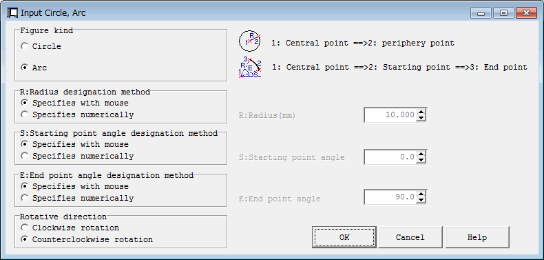
* "Insert Coodinates at Key","Insert Same Point","Next
Same Point","Insert-Grid ON/OFF"
The same function as "Insert Polyline" can be used.
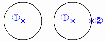
Example:
The left figure specifies radius numerically, carries out left mouse click of the central point by (1), and inputs circle.
The right figure carries out left mouse click of central point (1)
and the circumference upper part point (2), and inputs circle.
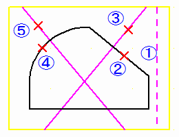
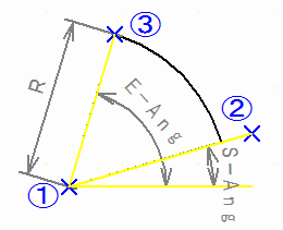
Example:
Carry out left mouse click to order of central point (1) and starting point angle extension upper part (2) and end point (3).
< Retun to Index > |
| |
|
| |
Insert Regular Polygon |
| |
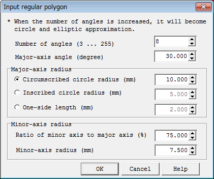
Input Regular Polygon (Line, Line with arrow, Dotted line, Dashed
line, Chained line, Surface) set up by line of "Set comment property".
When the number of angles is increased, approximate graphic of circle
and ellipse can be inputted.
* "Insert Coodinates at Key","Insert Same Point","Next
Same Point","Insert-Grid ON/OFF"
The same function as "Insert Polyline" can be used.
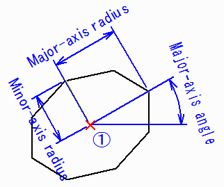
Example:
Specify "Number of angles" as 8, specify "Minor-axis
radius" to 75% to the major axis, specify "Major-axis angle"
as 30 degrees, and carry out left mouse click in (1).
< Retun to Index > |
| |
|
| |
Insert Free Curve |
| |
Input Free Curve (line, line with arrow, cloud mark) by contents
set up by line of "Set comment property".
Move mouse cursor to position of the starting point to input free
curve into, turn ON the mouse left button, move mouse in the state of ON,
and raise the mouse left button in position of end point.
< Retun to Index > |
| |
|
| |
Insert Offset Line |
| |
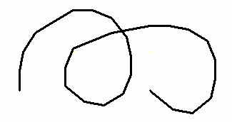
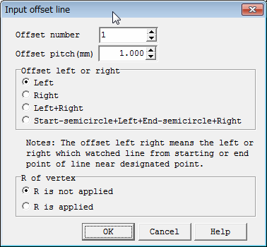
Offset line is polyline which the specified distance offset to already
inputted polyline.
Example:
The left figure is the result of seting next selecting and carrying
out left mouse click by (1).
"Offset number": 1, "Offset left or right":"Left+Right", "R of vertex": Don't apply.
The right figure is the result of seting next selecting and carrying
out left mouse click by (1).
"Offset number": 2, "Offset left or right":"Start-semicircle+Left+End-semicircle+Right",
"R of vertex": Attach.
< Retun to Index >
|
| |
|
| |
Insert Rectangle,Long Circle |
| |
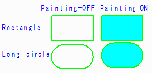
Input Rectangle or Long circle set up by "Set comment property".
* When "Convert to line" is checked by "Set comment property",
it will convert and input into polyline instead of figure type called Long
circle.
Although appearance at the input time is the same, since structures
of data differ, it is possible of shape change of polyline by edit.
* There exist click input mode and drug input mode.
Example:
The upper figure is input example in click input mode ON.
Click by the left mouse button in position of (1), and then click in position of (2).
Figure below is input example in click input mode OFF.
Where left mouse button down is carried out by (1), drag, and rise
by (2).
* "Insert Coodinates at Key","Insert Same Point","Next
Same Point","Insert-Grid ON/OFF"
The same function as "Insert Polyline" can be used in click input mode ON.
< Retun to Index >
|
| |
|
| |
Insert Text |
| |
Input text set up by "Set comment property".
* The string designation method
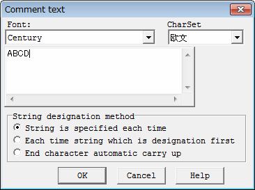
- Each time string designation
Whenever it carries out 1 string input, "Comment text"
dialog is displayed, and input string each time.
When ending, push cancel button in "Comment text" dialog.
- String of designation with each time beginning
When string is specified first, the same string is continued and it can input repeatedly.
Press Enter key, when ending.
- It is automatic carry up about character of end.
End's character automatic carrying advances within number group (0-9),
uppercase alphabet group (A-Z), and lower-case alphabet group (a-z).
When string is specified first, it will become number added one when the string last was number, and, in the case of the alphabet, the next alphabet of character code will be chosen automatically.
About carry, if character on the left of column which becomes carry
is the same group, left character will become carry automatically.
Digit number is the same.
Press Enter key, when ending.
Example:
018 ->019 ->020 ->021
A98 ->A99 ->A00 ->A01
12ZY->12ZZ->12AA->12AB
AAy ->AAz ->AAa ->AAb
"Insert Coodinates at Key","Insert Same Point","Next Same Point","Insert-Grid ON/OFF"
The same function as "Insert Polyline" can be used.
However, when "Each time string designation", the same next point does not function, unless it inputs some strings into next "String input Window".
< Retun to Index >
|
| |
|
|
Insert Bitmap |
|
Input Bitmap set up by "Set comment property".
Bitmap is read from image file.
Example:
Carry out left mouse button click by (1).
< Retun to Index >
|
|
|
|
Insert Macro
|
|
Input macro set up by "Set comment property".
Macro is read from input drawing file (HP-GL, PDF, DXF, DWG, GERBER,
NC-Drill, IGES, SXF, Image, or comment file).
Move mouse cursor to position to input Macro into, and click with the mouse left button.
Example:
Carry out left mouse button click by (1).
* "Insert Coodinates at Key","Insert Same Point","Next
Same Point","Insert-Grid ON/OFF"
The same function as "Insert Polyline" can be used.
< Retun to Index > |
| |
|
| |
Insert Dimension |
| |
Input dimension.
When dimension is inputted, it will become plural lines and text.
"Input Dimension" dialog is displayed.
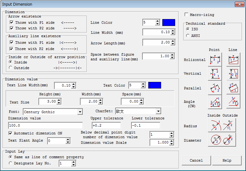
The following figures show name of dimension property.
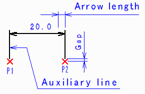
* Arrow existence
Specify whether arrow is applied or not.
Those with P1 side < -----
Those with P2 side <----->|
* Auxiliary line existence
Specify whether auxiliary line is applied.
Those with P1 side |<----->
Those with P2 side <----->|
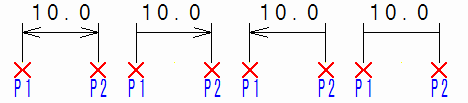
* Inside or Outside of arrow position
Specify whether arrow is applied inside or it applies outside.
Inside |<----->|
Outside ->|-------|
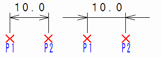
* Automatic dimension ON
When this is checked, string specified by "Dimension value"
is not used, but dimension value will be taken out automatically and it
will be inputted.
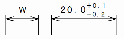
Example:
The left figure was inputted without automatic dimension OFF, dimension
value "W", upper tolerance, and lower tolerance nothing.
The right figure was inputted by automatic dimension ON, upper tolerance "+0.1", and lower tolerance "-0.2."
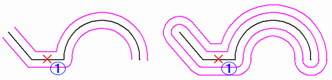
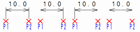
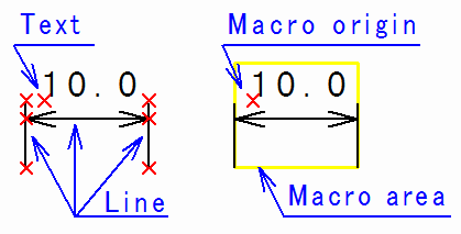
* Macro-izing
Dimension consists of line multiple in dimension line, and text multiple
in dimension value.
When check of Macro-izing is applied, that will be registered as Macro and the Macro will be inputted into the same position.
Control point of Macro turns into control point of dimension text.
As for file name, number of management is added to "*",
and external file does not exist really.
After Macro-izing, it breakups by Macro breakup and can return to plural lines and text.
When Macro-izing is unchecked, it will be inputted in plural lines
and text.
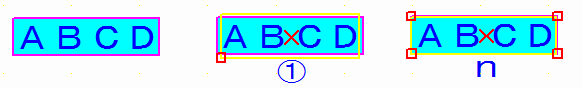
Example:
The left figure is dimension inputted by "Macro-izing"OFF.
The right figure is dimension inputted by Macro-ized ON.
X mark shows constituting points.
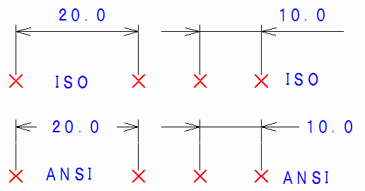
* Dimension technical standard
Select dimension technical standard from the next.
- ISO
- ANSI
* "Insert Coodinates at Key","Insert Same Point","Next Same Point","Insert-Grid ON/OFF"
The same function as "Insert Polyline" can be used in point
designation.
< Retun to Index > |
| |
|
| |
Select |
| |
It is turned mode which chooses comment. In addition, when having
already become selection mode, it is turned mode in which it does not choose.
When editing comment inputted, after turning it selection mode and selecting comment, edit command (Diaplay comment property, Change comment property, delete, move, rotate, scale up/down, macro-izing, macro breakup, connect window with surface, copy, cut, paste) is issued.
If selection mode is annotated, mouse will be moved, and x will be displayed if mouse cursor comes to constituting point of comment. Moreover, if mouse cursor comes on line, line color will change. If mouse cursor comes in area of rectangle, long circle, text, bitmap, or macro, then rectangle showing the area will be displayed.
Selection of comment, displays small square on constituting point
or area four corners. Moreover, color of line changes. Rectangle showing
the area is displayed on rectangle, long circle, and text.
Rectangle which shows the area is displayed on rectangle, long circle, text, bitmap, and macro.
As for selected comment, selection will be canceled, if edit command
is executed, other comments are recognized or ESC key is pushed.
The selection method of comment is shown below.
* Select
Select on conditions shown in the following set up by "Set Property".
- Selected graphic type
It is Select ON/OFF about L ine, Surface, Text, Rectangle/LongCircle, Bitmap, and Macro.
- Line Selection method
"Start to End Point" mode or "ControlPoint" mode
"Start to End Point" selects the starting point to end
point of polyline collectively by click somewhere on polyline.
Moreover, at the time of area Select, unless from the starting point
to end point of polyline is included in area, don't select.
"ControlPoint" mode will select the constituting points, when it clicks constituting points of polyline, and when it clicks line upper part, it will select constituting points of both edges of the line.
Moreover, recognize the constituting points in area that constituting
points of polyline are included at the time of area Select.
Example:
When (1) is clicked by "Start to End Point" mode, the starting
point to end point will be selected.
Example:
When (1) is clicked by "ControlPoint" mode, both-edges
point of line segment of (1) will be selected.
Then, pressing Shift key, when it clicks constituting points of polyline
of (2), additional select of the constituting points can be carried out.
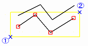
Example:
When (1)->(2) drug is carried out and area select is set by "Start
to End Point" mode, polyline which has all the constituting points
from the starting point to end point in area will be recognized.
Like polyline in the upper part, even if some constituting points
exist in area, the polyline does not recognize.
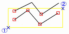
Example:
When (1)->(2) drug is carried out and area select is set by "ControlPoint"mode,
all the constituting points in area will be recognized.
- Selected area
It is effective at the time of area Select, and select one of "Inside of Area" or "Outside of Area".
When it has set to "Inside of Area", figure in area will
be selected.
When it has set to "Outside of Area", figure outside area
will be selected.
However, when "Line selevtion method" is "ControlPoint", it becomes in area automatically.
* Individual Select
It will select, when comment is pointed out with the mouse left button.
When the next comment is selected, before selected comment will become
select release.
Please select to select the next comment, pressing Shift key without carrying out select release of the before selected comment.
It will become select release when before selected comment is pointed
out pressing Shift key.
Next Same Point
When figure is crowded, nearby, another figure may be recognized.
Then, press "n" key, or press the right mouse button, take out context menu, and select "Next Same Point" menu, after select individual comment .
Then, recognize nearby, another figure.
Figure with the another neighborhood can be recognized by repeating
the same operation.
When nearby figure is lost, message "Data is not found !" comes out.
* Rectangular area select
Drag between two diagonals of area to select with the mouse left
button (turn ON the mouse left button by the 1st point, move mouse in the
state of ON, and turn OFF the mouse left button by the 2nd point).
Then, comment in the area is selected.
When the next comment is selected, before selected comment will become
select release.
Please select to select the next comment, pressing Shift key without
carrying out select release of the before selected comment.
It will become select release when before selected comment is recognized pressing Shift key.
Example:
When it drags to (2) from (1) by rectangular area select, all the
polylines will be selected to select only lower right figure with the left
figure.
Then, when it drags to (4) from (3) by rectangular area Select, pressing
Shift key, select of upper left rectangle will be released.
Result becomes right figure.
* Polygon area select
It clicks at vertex of polygon area to select with the mouse left button (button is lowered and raise quickly in the same position of mouse), and when the last presses Enter key or nearby of the 1st vertex is pointed out, it will close polygon.
Then, comment in polygon area is selected.
When BackSpace key is pressed while polygon input, vertex before
one is cancellable.
When Esc key is pressed while polygon input, polygon area select is cancellable.
The number of the maximum vertexes which can be inputted is 20 pieces.
When the next comment is selected, before selected comment will become
select release.
Please select to select the next comment, pressing Shift key without carrying out select release of the before selected comment.
It will become select release when before selected comment is recognized
pressing Shift key.
Example:
When (1) to (7) is clicked by polygon area select at the left figure,
as shown in the right figure, figure in polygon can be selected.
* Move selected comment with mouse
First, select comment by the above-mentioned method.
Next, move mouse cursor onto any one of the selected comments, the mouse left button is downed, move mouse in the state of down, and raise the mouse left button in position after movement.
Example:
When left-hand side figure is selected and it drags to (2) from (1),
it will move to the right.
* Mouse copies recognized comment
First, select comment by the above-mentioned method.
Next, moving mouse cursor onto any one of the selected comments,
and pressing Cntl key, the mouse left button is downed, move mouse in the
state of down, and raise the mouse left button in position after movement.
* Shape movement of comment (deformation)
In the state where button is not pushed, operate mouse cursor to
position of comment which carries out shape distortion, and display recognition
mark.
At this time, if it is constituting points of polyline, rectangle, and long circle, x mark will be displayed.
If it is on line of polyline, color of line will change.
If it is edge of area of rectangle, long circle, and Bitmap, straight
line will be displayed around there.
In this state, turn ON the mouse left button, move mouse in the state of ON, and raise the mouse left button in position after shape distortion.
Contents which can deform by this command.:
Polyline:Individual movement of constituting points, and movement
of the whole polyline.
Rectangle, Long circle:Point movement of four corners, four sides line movement
Bitmap:Point movement of four corners, four sides line movement
Example:
The mouse left button is downed by polyline constituting points (1)
by the following figure, move mouse to (2) in the state of down, and raise
the left button.
* Comment property change Select
Property can be changed when comment is double-clicked with the mouse
left button.
"Set comment property" dialog appears.
Here, property will be changed, when property to change is set up
and OK button is pushed.
In addition, about text, "Comment text" dialog is displayed and string can be changed.
Property change of others of text should use "Edit-Change Property"
menu.
* Next Same Point
Another figure may be selected when target figure is selected by
individual Select in place where figure is crowded.
Then, press "n" key immediately after selecting, or press the right mouse button, take out context menu, and select "Next Same Point" menu.
Then, reselect nearby, another figure.
The same operation is repeatable until it becomes impossible to recognize
nearby figure.
When there is no nearby figure, message "Data is not found !" comes out.
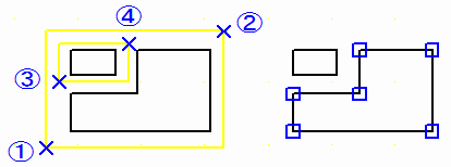
Example:
In the left figure, text has overlapped on rectangle.
Although he wants to select rectangle, recognize text to click central
point (1), as shown in middle figure.
Then, push on "n" key will select rectangle which exists in the next, as shown in the right figure.
< Retun to Index > |
| |
|
| |
|
| |
All comments are chosen. Same thing is made even if it presses key of Ctrl and A simultaneously.
< Retun to Index > |
| |
|
| |
|
| |
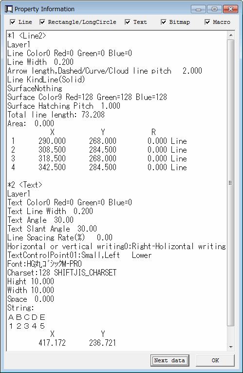
Display the property of selected comment as text.
This Window can always be displayed, unless OK button is pushed.
< Retun to Index > |
| |
|
| |
|
| |
Property of selected comment is changed.
Since "Set comment property" dialog will be displayed if
this menu is specified, property to change here is set up.
The following is dialog when text is selected and attribute changing
menu is selected.
* Re-read of Bitmap
When the contents of Bitmap file are changed, update the contents
of the newest file when it re-reads,
* Re-read of Macro
When the contents of Macro file are changed, update the contents of the newest file when it re-reads,
A push on OK button will change comment data only attribute value
changed among attribute values displayed in this dialog.
< Retun to Index > |
| |
|
| |
Delete |
| |
The selected comment is deleted.
The same thing is made also by the Delkey.
< Retun to Index > |
| |
|
| |
Move |
| |
When this menu is selected, "Move" dialog will be displayed,
and selected comment will be moved or copied.
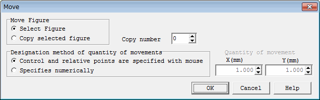
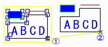
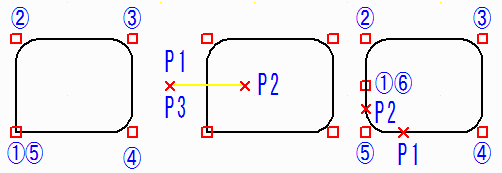
Example of move:
Select "Control and relative points are specified with mouse"
of "Designation method of quantity of movements".
The left figure which consists of line, rectangle, and text is selected, and result of having specified control point (1) and relative point (2) with mouse is the right figure.
< Retun to Index > |
| |
|
| |
Rotate,Scale Up/Down |
| |
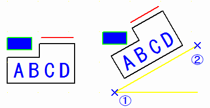
Rotation, zooming, copy of selected comment.
Dialog of "Rotation and Zooming" of comment is displayed.
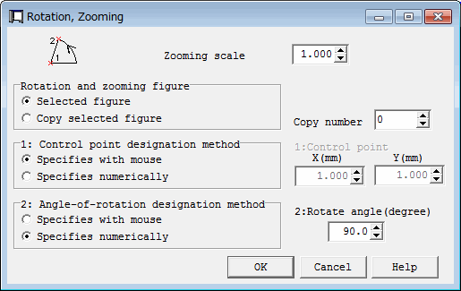
Example of rotation:
Result of having specified control point (1) and angle-of-rotation
point (2) with mouse is the right figure about the left figure which consists
of polyline, Rectangle, and text.
< Retun to Index > |
| |
|
| |
Divide/Delete/Move/RouteChange Polyline section |
| |
Perform dividing, deletion, and movement and route change for the
section of polyline.
* Divide line
As shown in the left figure, carry out left mouse click of section
constituting-points (1)(2) of polyline to divide.
Then, since "Edit line section" dialog appears, select "Divide line" and push OK button.
Then, as shown in the right figure, polyline to (1)-(2) passes away,
and it becomes two polylines.
Carry out left mouse click of the vertex to divide twice to divide
at one polyline vertex.
This polyline will be deleted when the starting point and end point of polyline are pointed out.
* Delete control points
As shown in the left figure, carry out left mouse click of section constituting-points (1)(2) of polyline to delete.
Then, since "Edit line section" dialog appears, select
"Delete control points" and push OK button.
Then, as shown in the right figure, constituting points to (1)-(2)
are deleted.
Carry out left mouse click of the vertex to delete twice to delete one polyline vertex.
This polyline will be deleted when the starting point and end point of polyline are pointed out.
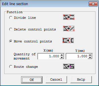
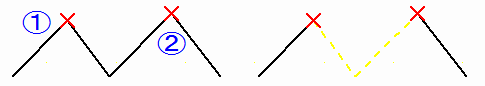
* Move control points
As shown in the left figure, carry out left mouse click of section
constituting-points (1)(2) of polyline to move to.
Then, since "Edit line section" dialog appears, select "Move control points", specify the quantity of movements numerically, and push OK button.
Then, as shown in the right figure, constituting points to (1)-(2)
are moved.
Carry out left mouse click of the vertex to move to twice to move
one polyline vertex.
* Route change
As shown in the left figure, carry out left mouse click of section
constituting-points (1)(2) of polyline which wants to set route change.
Then, since "Edit line section" dialog appears, select
"Route change", and push OK button.
And input new route in way of polyline input (the following figure "a" key, (3)(4) left mouse click), and finally press Enter key, or carry out left mouse click of the position of (2).
Then, midcourse route can be changed as shown in the right figure.
When Enter key is pressed after (1)(2) left mouse click, between
(1)-(2) will be directly connected with straight line.
< Retun to Index > |
| |
|
| |
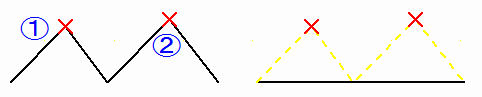
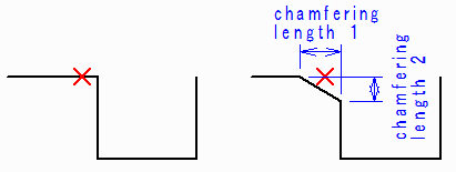
Shape Change of Polyline Vertex |
| |
On vertex of polyline, insert arc or chamfer.
Selecting this menu will display "Change line vertex" dialog.
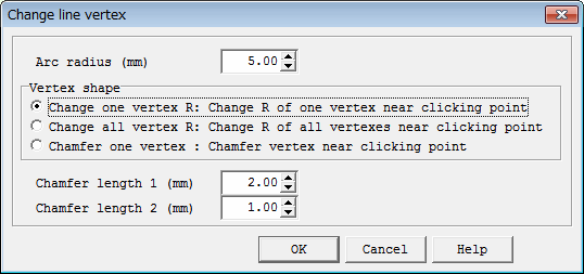
* Change one vertex R
Change vertex near clicking point into arc specified by R.
Designation of R= 0 will change arc into vertex.
When it clicks arc upper part, it will change into R which specified
radius of the arc.
Arc can be inserted with a radius of designation also between arc,
and between lines and arcs.
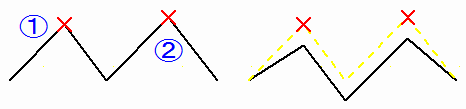
* Change all vertex R
Change all the vertexes of polyline near clicking point into arc
of specified R.
Designation of R= 0 will change arc into vertex.
When there exists arc which is not vertex, it is changed into R specified by radius of arc.
Arc is not inserted between arc, and between lines and arcs.
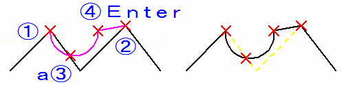
* Chamfer one vertex
Chamfer by chamfering length 1 and 2 on vertex near clicking point.
When a little clicking point is shifted to vertex, clicking point side will become chamfering length 1.
And the side opposite to becomes chamfering length 2 to vertex.
< Retun to Index > |
| |
|
| |
Delete line in selected area boundary |
| |
Delete polyline on selected area boundary.
Perform rectangular area selecting or polygon area selecting for
polyline after selecting this menu.
Then, since "Execute line deletion on selected area boundary."
dialog is displayed, line deletion will be executed when OK button is pushed.
Example: Rectangular area deletion
Drag to (1)->(2) by the left mouse button with the left figure.
A push on OK button will delete line in rectangular area, as shown
in the right figure.
Example: Polygon area deletion
Carry out left mouse button click with the left figure at order of
(1) - (11).
A push on OK button will delete line in polygon area, as shown in
the right figure.
Example: Use polygon area deletion and it is knife cutting.
The left figure is Rectangle converted and inputted into polyline.
Constituting points are (1)-(5).
When R is applied to vertex by "Change all vertex R", R
will not attach this polyline to (1)(5) of the starting point and end point.
Then, as shown in middle drawing, when left mouse click is carried
out to P1, P2, and P3 by polygon area deletion, as cut with knife, line
segment between (1)-(2) will be divided into two.
Then, when arc radius is specified, left mouse click is carried out by P1 and P2, as shown in the right figure, and line connection is executed, R will be applied to all the vertexes.
< Retun to Index > |
| |
|
| |
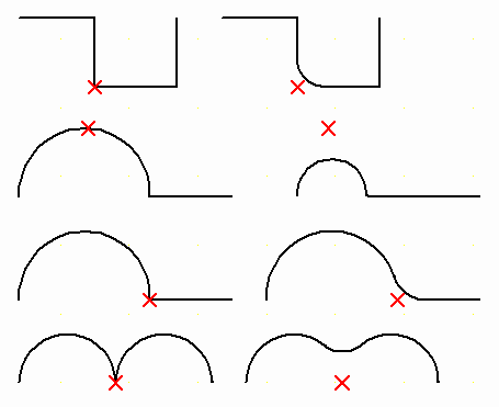
Trim Line |
| |
Trim line segment by the side of designation on point of intersection
of polyline and polyline.
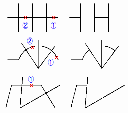
* Line segment trim of edge
As shown in the above figure and middle figure, when left mouse click
is carried out on edge line(1) of polyline, it will be trimmed in crossing
line segment near clicking point.
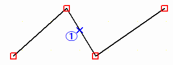
* Trim line segment to edge after the specified line segment
As shown in the figure at the bottom, when left mouse click is carried out by median line part (it is not edge) upper (1) of polyline, it will be trimmed by crossing line segment near clicking point, and subsequent polylines will be deleted.
* Trim by two lines in line segment
At place of (2) of the above figure and middle figure, there are
two line segments crossing one line segment.
When left mouse click is carried out by (2) (on line segment between the two), it will be trimmed by two line segments and between two line segments will be deleted.
< Retun to Index > |
| |
|
| |
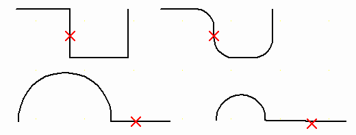
Connect Line |
| |
Connect endpoint (the starting point or end point) of two polylines
on extension, and set it one polyline.
Selecting this menu will display "Arc inserted in line connection
point" dialog.
Specify arc radius, when inserting arc in connection point.
When not inserting arc, leave arc radius zero.
Push OK button and carry out left mouse click of end line upper part
of polyline to connect.
Then, it connects on extension and becomes one polyline.
Cautions 1:
In the case of single line which consists of only the starting point
and end point, endpoint of direction near clicked position moves and is
connected.
Cautions 2:
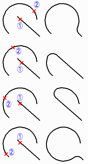
When either is arc and both are arcs, connection path has more than one.
Plural routes can be changed and selected at point clicked to the
2nd.
Before clicking to the 2nd, when cursor is brought to end of line
segment in the state of mouse button rise, route will be displayed by dragging.
When mouse cursor is brought to the next constituting points from end of the 2nd line segment, the next connection path will be displayed by dragging.
Please carry out left mouse click and decide in position of route
of hope.
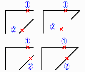
Example:
Connect between straight line-straight line by radius zero.
When left mouse click is carried out to (1)(2) with the left figure, line will be connected as shown in the right figure.
Position of (2) is different in the above figure and below figure.
Endpoint near position of (2) moves.
Example:
Between straight line-straight lines, insert arc and connect.
When left mouse click is carried out by (1)(2) of the left figure, line will be connected as shown in the right figure.
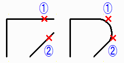
Example:
Connect by radius zero between arc-straight lines.
When left mouse click is carried out by (1)(2) of the left figure,
line will be connected as shown in the right figure.
Position of (2) is different in the upper figure and below figure.
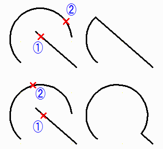
Example:
Between arc-straight lines, insert arc and connect.
When left mouse click is carried out by (1)(2) of the left figure,
line will be connected as shown in the right figure.
It is between the upper and lower sides of figure, position of (2) is different.
< Retun to Index > |
| |
|
| |
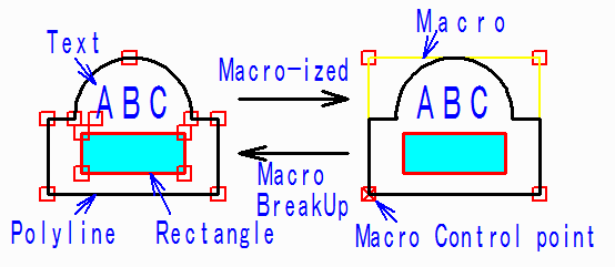
Macro-izing |
| |
Macro-ize selected comment.
When it Macro-izes, it will become convenient to set plural figures
into one and to handle them (addition, deletion, movement, etc.).
In "Macro BreakUp" , macro is breaked up and it can return
to the original figure.
The contents of Macro-ized:
When it Macro-izes, Macro of the following contents will be created,
and it is inputted so that the Macro may be displayed on the same position
as Macro-izing before.
Scale : 1.0
Angle : 0 degree
File name :
Number which begins from 1 after text of "*" is
added.
Number is ID number for distinguishing from another Macro.
This file name is not file which exists really.
Control point:
Lower left point of constituting points of figure in Macro.
Example:
It will become the right figure, when polyline, text, and rectangle of the left figure are selected and Macro-izing is performed.
Reversely, it will become the left figure, when Macro is selected
and Macro breakup is carried out with the right figure.
< Retun to Index > |
| |
|
| |
Macro breakUp |
| |
BreakUp Macro of selected comment.
Although appearance looks the same as breakup before, since it has
breakupped, figure which existed in Macro can edit each figure.
< Retun to Index > |
| |
|
| |
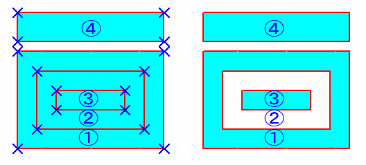
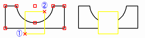
Connect window with surface |
| |
When there exist plural surfaces of selected comment, set the 1st
surface into parents, and connect surface of the 2nd after as a window.
* Painting of surface which connected window
When there exist window included by parents' surface and window included
by the including window, painting becomes repetition of ON, OFF, ON, OFF
... from the outside.
As for parents and window, painting is set to ON when window exists
on the outside of parents' surface.
Example:
Four surfaces are inputted into the left figure from (1) to (4).
When these four surfaces are selected and this command is executed, as shown in the right figure, four surfaces will be connected, and painting ON and OFF will be given.
* Method to release connection of window
Select surface which wants to release connection and set up surface
attribute value of polyline for carrying out nothing by "Change comment
property".
Then, it becomes polyline without painting out.
Connection is also released.
And select the polyline once again and set surface attribute value
of polyline as Solid Painting (either except nothing) by "Change comment
property".
< Retun to Index > |
| |
|
| |
Copy,Cut,Paste |
| |
* Selected comment is copied to clipboard. Same thing is made even if it
presses key of Ctrl and C simultaneously.
* Selected comment is cut off to clipboard. Same thing is made even if it presses key of Ctrl and X simultaneously.
* Comment in the clipboard is pasted. Same thing is made even if it presses
key of Ctrl and V simultaneously. Moreover, same thing is made even if
it presses the key of Shift and Ins simultaneously.
< Retun to Index > |
| |
|
| |
|
| |
The line of the result searched with "Line connection search"
is changed into polyline of comment.
If this function is used, it will become enabling to save search
results in form of comment, and to add comment to it or to modify to it.
Input layer becomes the same as the present page number.
< Retun to Index > |
| |
|
| |
|
| |
Convert viewdata into comment data.
Although it can perform seeing, printing or carrying out data conversion
of the viewdata, but, addition editing of the figure cannot be carried
out.
When viewdata seen now is converted into comment data, figure can
be added or it can edit.
Selecting this menu will display "Comment-izing of viewdata" dialog.
Here, when "Drawing Area" and "Layer" are set
up and OK button is pushed, viewdata will be converted and displayed on
comment data.
Since it becomes the same display, it is not almost different from
viewdata seemingly.
It will be overwritten by it if comment data has already existed.
* Drawing Area
Select from "All of Draw" or "ZoomArea of UpperWindow" of viewdata.
When figure is trapped in zoom area boundary in case where "ZoomArea
of UpperWindow" is selected, polyline clips, but surface, text, and
Bitmap do not clip.
* Layer
Select from the following layer inputted into viewdata.
- Sets with page number
- Based on comment property set
- Layer number designation
Specify layer number inputted here.
< Retun to Index > |
| |
|
| |
Display |
| |
* The same function as PloView product page can use it also for comment.
Display command
Thumbnail display
* The same function as PloComp product page can use it also for comment.
Display command
Setup display ON/OFF of files and pens, and Display in piles/Display in arranges
Thumbnail display
< Retun to Index > |
| |
|
| |
Setup of pen |
| |
* The same function as PloView product page can use it also for comment.
Setup of pen
* The same function as PloComp product page can use it also for comment.
Setup of pen
< Retun to Index > |
| |
|
| |
Text font |
| |
* The same function as PloView product page can use it also for comment.
Text font
* The same function as PloComp product page can use it also for comment.
Text font
< Retun to Index > |
| |
|
| |
Request |
| |
* The same function as PloView product page can use it also for comment.
Measurement of distance between lines, and angle
* The same function as PloComp product page can use it also for comment.
Measurement of distance between lines, and angle
< Retun to Index > |
| |
|
| |
Output |
| |
Viewdata and comment data can be outputted in piles.
Or only comment data can be outputted.
* The same function as PloView product page.
Output to printer, plotter
Various file outputs
* The same function as PloComp product page.
Output to printer, plotter
Various file outputs
< Retun to Index > |
| |
|
|
Contact us
|
|

Return to Index |
|