|
|

| |
This HP describes the PloView series products of Viewer and Converter which display, edit, and convert various graphic files (HP-GL, HP-GL/2, HP RTL, PDF, DXF, DWG, GERBER, NC-Drill, IGES, SXF, TIFF, JPEG, BITMAP, EMF, PCX, FPX, PNG, GIF). |
|
|
|
 Index Index |
|
Outline
Product list
Functional outline of product
Operation conditions
Trial, order, and use
Maintenance of PloView series
Supporting graphic file of PloView series
Introduction of automatic processing combining various products
Problem about color, and solution
Q&A
The newest information
Contact us
|
|
|
|
Outline
|
|
Recently, all designs were performed by CAD, it was electronized, drawing
was kept in electronic drawing warehouse, and it became natural to carry
out electronic release of drawing. However there may be many related people
in the distance, electronic drawing warehouse can be searched in an instant,
and drawing can be seen. Highly efficient and cheap viewer for seeing drawing
electronized in such a situation constitutes big key component.
PloView is a low-cost, high-performance viewer based on Hewlett-Packard's
HP-GL (Hewlett-Packard Graphics Language) which is a plotter control language
for drawing creation that is popular as the de facto standard. PloView
can read not only HP-GL but very many Graphic format files, and can carry
out displaying, marking, printing, and data conversion. And it has about
the same powerful input editing function as 2D-CAD, and design drawing
is diverted and another drawing can be created easily.
PloView has been used by many customers since the first release in 1995,
and has repeatedly upgraded in response to customer's request.
Our customers include manufacturers of automobiles, shipbuilding, electrical products, mechanical products, and the parts that compose them, as well as large to small and medium-sized businesses that handle drawings for maps, roads, public facilities, buildings, and plants.
The number of companies that ordered PloView series products in Japan exceeded
1500 companies.
Return to Index |
| |
|
|
Product list
|
|
PloView series has the following products.
| Product name |
Fee of 1 license |
Function |
| PloViewMini |
0 US$ |
Viewer with limited functions only for display of HP-GL (HP-GL/2, HP RTL not supported) from PloView. |
| PloView |
70 US$ |
Viewer which looks at one HPGL/Vector/Image drawing simultaneously. |
| PloComp |
90 US$ |
Viewer which looks at plural HPGL/Vector/Image drawings in piles (arranging)
simultaneously. |
| PloCon |
70 US$ |
HPGL/Vector/Image drawings are continuously output to the printer (not
displayed). |
| PloViewAuto |
950 US$ |
Efficient continuous automatic conversion of many HPGL/Vector/Image drawings
(one drawing can be opened at the same time) into various file formats. |
| PloCompAuto |
950 US$ |
Efficient continuous automatic conversion of a large number of HPGL/Vector/Image
drawings (multiple drawings) into various file formats, and continuous
automatic output by adding a change area (cloud mark) after drawing comparison. |
| PloCVAuto |
0 US$ |
Output after automatic drawing comparison of two new and old multi-page
files.
PloCVAuto is free, but requires PloCompAuto and PloViewAuto licenses. |
If product name is clicked, it will jump to page of detailed explanation of the product and download.
All the functions can be used for 30 days free of charge for evaluation.
Return to Index |
|
|
|
Functional outline of product
|
|
Functional comparison of product *:exist,
-: nothing
|
PloView
Mini |
PloCon |
PloView |
PloComp |
PloView
Auto |
PloComp
Auto |
Input:
HP-GL,HP-GL/2,HP RTL,PDF,DXF,DWG,
GERBER,NC-Drill,IGES,SXF,EMF,
TIFF,JPEG,Bitmap,PCX,FPX,GIF,PNG |
HP-GL only |
* |
* |
* |
* |
* |
Output:
HP-GL,HP-GL/2,HP RTL,PDF,
DXF,DWG,IGES,SXF,EMF,WMF
TIFF,JPEG,Bitmap,PCX,FPX,GIF,PNG |
- |
- |
* |
* |
* |
* |
| Manual data convert |
- |
- |
* |
* |
* |
* |
| Auto data convert : Single file |
- |
- |
- |
- |
* |
* |
Auto data convert :
Multiple file overlap, change area |
- |
- |
- |
- |
- |
* |
| Manual print out |
- |
- |
* |
* |
* |
* |
| Auto print out |
- |
* |
- |
- |
* |
* |
| Number of simultaneous open files |
1 |
1 |
1.. |
20 |
1.. |
20 |
| 1 file multi-page display |
* |
- |
* |
- |
* |
- |
| Display file pile up and arranging |
- |
- |
- |
* |
- |
* |
| Display mode (Copy,Merge,xOr,BW/Color) |
* |
- |
* |
* |
* |
* |
| Display rotate, mirror |
* |
- |
* |
* |
* |
* |
| Diaplay thumbnail |
- |
- |
* |
* |
* |
* |
| Convert view file to comment file |
- |
- |
* |
* |
* |
* |
| Edit vector data (comment) |
- |
- |
* |
* |
* |
* |
| Drawing comparison, add cloud mark to change area |
- |
- |
- |
* |
- |
* |
| Measuring, search |
- |
- |
* |
* |
* |
* |
| Fee of 1 license ( US$ ) |
0 |
70 |
70 |
90 |
950 |
950 |
Return to Index |
|
|
| |
Operation conditions |
| |
Personal computer of Intel compatible CPU mounting
- Empty capacity of memory: 2GB or more
- Empty capacity of hard disk drive: 2GB or more
- Screen resolution: 1024 dots x 768 dots Above
- OS: Windows 7, 8, 10 and 11 32Bit, 64Bit
- It is necessary to install some printer drivers.
Printer driver of high resolution is required to read PDF file.
- It is necessary to install free software "ODA File Converter" at input and output of DWG file.
- When outputting EMF file, it is necessary to set the following settings of
Windows to the initial values.
"Start" "Settings" "System" "Display"
"Scale and layout" 100% (initial value)
Return to Index |
| |
|
| |
Trial, order, and use |
| |
Since PloViewMini is free of charge, this item is excluded.
Step1. Trial
Please download product from HP of each product. Since product is compressed into ZIP file, please extract it with suitable extracting software. Readme.txt file should be in extracted inside, and since product summary, the installation method, the uninstallation method, license agreement, licensing fee, protection release, reference, and version upgrade history are described in it, please read well. And, there is a file called "Setup<AppName>.exe" in the decompressed file. Double click on the file in Explorer to install it. Product currently released on HP doubles both as trial edition and the formal version. All the functions can be used free of charge for 30 days from installation for trial. If passed 30 days and do not enter a password, it will not work will be protected. When you use more, please send me order of the formal version.
Step2. Order of formal version
Please remit licensing fee described in the above product list to PayPal.
In PayPal, it can pay with credit card.
Credit card payment enables at the next HP.
PloView ... https://www.isoplotec.co.jp/eploview.htm#Licensing fee
PloComp ... https://www.isoplotec.co.jp/eplocomp.htm#Licensing fee
PloCon ... https://www.isoplotec.co.jp/eplocon.htm#Licensing fee
PloViewAuto https://www.isoplotec.co.jp/eploviewauto.htm#Licensing fee
PloCompAuto https://www.isoplotec.co.jp/eplocompauto.htm#Licensing fee
Please carry out following HP reference about PayPal.
And please send us the following order form by e-mail. The e-mail address
is listed at the end of this page.
Order sheet
1. Soft name: English PloView/PloComp/PloCon/PloViewAuto (Please
select)
2. Soft version no.:
3. Order quantity:
4. Company name:
5. Offer person name:
6. Offer person E-mail ID:
7. Charge payment day:
8. Charge payment amount:
Step3. Sending of password
The copyright holder will email the password when payment of the registration
fee has been confirmed.
Please copy and install up to the number you ordered.
Step4. Lock release of software :
If you are evaluating within 30 days of installation, right-click the product
program in Explorer to bring up a pop-up menu, select "Run as administrator"
to launch the product, and go to Help-Version Information. Please display
the "Version Information" dialog and enter the password. If you
start the product without selecting "Run as administrator", the
following "Warning screen prompting you to start the product as an
administrator" will be displayed, so please try again.
When the evaluation period has expired, the following dialog will be displayed.
Password setting Dialg
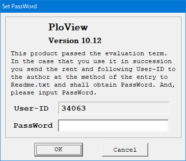
If you enter the password in this Dialog, you will get the following warning message.
Warning Dialg prompting you to start the product as an administrator
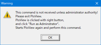
Click the "OK" button to finish.
Right-click the program of the product in Explorer to bring up the pop-up menu, and select "Run as administrator" to start the product. The "SetPassWord" dialog will be displayed. Enter the password.
Note:
- PloView series product licenses are permanently available for the same version.
- OS exchange, or exchange of installation personal computer
Even if you replace exchange of OS, or installation personal computer, given password can release lock.
However, the number which can install product in personal computer simultaneously is not exceeding ordered number.
- Revision up (rise of the 2nd place of decimal point of version number)
Revision up is free of charge.
Please download the revision software newer from HP and reinstall
it.
Previous password is effective.
- Definition of version upgrade and revision up
Example with version number 12.34
Upgrading is a case where the upper digit of the version number including the decimal place first rises, and in this example, the value of 12.3 changes.
The revision up is the case where the lower digit of the version
number including the second decimal place rises, and in this example, the
value of 4 changes.
Return to Index |
| |
|
| |
Maintenance of PloView series |
| |
PloView series products do not have a paid maintenance agreement.
For evaluation including the quality of this software, we have a free use period of 30 days.
We will accept inquiries about the latest version of this software, such as its functions and usage, free of charge via e-mail.
We will also accept information about problems with this software from customers via e-mail, and will make efforts to correct them free of charge. However, we cannot guarantee that we will be able to correct all problems.
At the same time as the new version was released, the maintenance of the old version will be terminated.
If you wish to maintain, please obtain a license for the new version (charged).
Return to Index |
| |
|
| |
Supporting graphic file of PloView series |
| |
PloView series supports to many Graphic files shown below.
Input: HP-GL, HP-GL/2, HP RTL, PDF, DXF, DWG, GERBER, NC-Drill,
IGES, SXF,
EMF, TIFF, JPEG, Bitmap, PCX, FPX, GIF,
PNG
Output: HP-GL, HP-GL/2, HP RTL, PDF, DXF, DWG, IGES, SXF, EMF, TIFF,
JPEG,
Bitmap, PCX, FPX, GIF, PNG, printer,
plotter, WMF, PS, EPS, SVG,
XPS, PCL
Details are described about "Support graphic file of PloView series".
In addition, it supports to comment file (CMT) which can read and write only PloView and PloComp.
Note: It is necessary to install free software "ODA File Converter" in input and output of DWG file.
Return to Index |
| |
|
| |
Introduction of automatic processing combining various products |
| |
By combining several products, you can compare the same pages in two multi-page PDF files and get one multi-page PDF file with changed areas (cloud marks).
1. Manual “Drawing comparison of multi-page PDF files”
Although it is all manual work, it is possible by the following operation using normal version PloComp and normal version PloView.
2. Automated "Drawing comparison of multi-page PDF files"
PloCVAuto automatically processes by sequentially starting PloCompAuto, PloComp attached to PloCompAuto, and PloView attached to PloViewAuto.
Return to Index
|
| |
|
|
Problem about color, and solution |
|
It may be unable to display well with combination of color of line, color
of surface, and background color which are used for drawing data.
Solution at that time is explained.
1. Line and background color
Subject :
If line color and background color is same, line will disappear.
For example, as shown in A figure, when color of line is black, if background color is white as shown in B figure, line is visible, but if background color is black as shown in C figure, line will disappear.
Solution :
(1) In PloView, since background color is changeable by setup, please change and be visible.
(2) When you do not want to change background color, and setup of "Color is changed when pen color is same color as background" is turned ON, it comes to be visible as shown in D figure.
2. Line on surface, and background color
Subject :
When line exists on surface, colors of the surface and line differ, and
background color changes, contents which you view will change. Therefore,
it does not seem that you wish depending on situation.
For example, as shown in E figure of the following figure, when black line
is on white surface, if background color is white as shown in F figure,
surface is not in sight, but line is visible. Surface and line are visible,
if background color is black as shown in G figure. If setup of "Color
is changed when pen color is same color as background" is turned ON
as shown in H figure, although surface is in sight, line will disappear.
Solution :
Please change background color by PloView or turn OFF setup of "Color
is changed when pen color is same color as background" so that figure
of hope appears.
3. Display mode and background color
Subject :
Display mode of PloView and PloComp has overwrite(Copy) and mixed color(Merge).
Overlapping color changes with the display modes and background colors.
As for overprint function of PDF in which PloView series supports, background
color is white and display mode is mixed color(Merge).
Solution :
Please understand phenomenon.
And when not becoming color of hope, color of figure which changes or piles up background color is adjusted.
4. When two or more pile surface has become
Subject :
By GARBER data, as shown in the next figure, it may have overlapped also with many piles.
Although normally displayed in overwrite (Copy) displaying, inner figure disappears in mixed color (Merge).
Solution :
Please display by overwriting (Copy).
If Merge is not used when displaying plural drawing in piles by PloComp,
lower drawing will disappear. In such a case, please select "set"
"pen" menu and set "Display procedure" to "Momentary
display 2". However, this function supports only screen display and
image outputs, such as TIF, JPEG, and BitMap. "Momentary display 1"
of PloComp will be the specified DrawMode(mixed color etc.), also when
piling up file in file. "Momentary display 2" draws inside of
each file by Copy, and when piling up file, it is set to the specified
DrawMode(Merge etc.).
Return to Index |
|
|
|
Q&A
|
|
| Q: |
Is the password of PloView, PloComp or PloCon effective, in the case that I replaced OS or personal computer? |
| A: |
Passwords are invalid for Version 8.0 or before.
For Ver.9.0 or later the password is valid.
Ver.8.0 or before, the user ID becomes new user ID and the password corresponding
to it is necessary. When the version is same, you are able to have a new
password issued gratuitously for 4 years, after you order. In such a case,
you need to communicate the reason, new old user ID and soft name to the
author with the electronic mail. In the case that you uninstall PloView,
PloComp, PloCon and installed PloView, PloComp, PloCon of the same version
in the same personal computer once again, the user ID does not change.
And the password of before is effective. PloView, PloComp, and PloCon of
another version (when column of the 1st place of version number decimal
point goes up) are charge, user ID differs, therefore passwords also differ.
|
| Q: |
Do the password of PloView, PloComp, PloCon differ every the personal computer? |
| A: |
It becomes the all same password after Ver.9.0.
Ver.8.0 or before, the password corresponding to the user ID is necessary.
|
| Q: |
When the personal computer breaks, can I receive PloView, PloComp, and PloCon of the old version? |
| A: |
It cannot do. It is only the newest version which is exhibited by HP. Therefore,
when you download PloView, PloComp, or PloCon first, please carry out backup
copy of the downloaded file. |
| Q: |
Why is it to not display the picture even if PloView, PloComp read the HP-GL file? |
| A: |
There is the possibility that the color of the background of the screen
and, the color of the pen that draw it are same. When it paints it with
the pen of the same color as the background the picture does not display
it. As for the case, please change the color of the background or, the
color of the pen with the set pen menu.
Please refer to Subject and solution about color for details. |
| Q: |
How do the color of the background of the screen of PloView, PloComp change it? |
| A: |
Please take out the SetPen dialog with the set-pen menu. Please change
background Pen No. |
| Q: |
Please tell me method to output so that text in file which performed DXF
(or DWG) output by PloView (or PloComp) can be edited as a text by CAD. |
| A: |
When "Set-Text" menu is selected by PloView (or PloComp), "Set Text"dialog will appear.
Here, select "Windows Font" by "Select Font".
Push OK button now.
And please perform DXF (or DWG) output. |
| Q: |
Although PloView and PloComp do not start on the personal computer with which the printer driver is not installed, what should it carry out? |
| A: |
PloView and PloComp go to see the setting value of the printer at the time
of starting. Therefore, unless the printer driver is installed, it cannot
start normally. Please install some printer driver.
The printer does not necessarily need to connect. |
| Q: |
User ID changes on the way and the protection starts. Please teach the solution. |
| A: |
Please log in by "Administrator" and install and in the state, please start and enter password. |
| Q: |
What to do if you get the message "The app you're to install isn't
a Microsoft-verified app" during installation |
| A: |
Click "Change my app recommendation settings."
This will take you to the "Apps & features" settings screen, where you should select "Anywhere" for "Choose where to get apps."
Then, the message "The app you're to install isn't a Microsoft-verified app" will no longer appear during subsequent installation operations. |
Return to Index |
|
|
|
The newest information
|
|
| Date |
The contents of updating |
| Jan. 02, 2019 |
PloComp Ver.10.08 was updated. |
| Jan. 23, 2019 |
PloView, PloViewAuto Ver.10.10 was updated.
PloComp, PloCon Ver. 10.10 was released.
|
| Feb. 02, 2019 |
PloView, PloComp Ver.10.10 were updated. |
| Mar. 02, 2019 |
PloView, PloComp Ver.10.10 were updated. |
| Mar. 26, 2019 |
PloView Ver.10.10, PloComp Ver.10.10, PloCon Ver.10.10 were updated. |
| May. 07, 2019 |
PloView Ver.10.10 was updated. |
| May. 08, 2019 |
PloCon Ver.10.10 was updated. |
| Jun. 01, 2019 |
PloView Ver.10.10, PloComp Ver.10.10, PloCon Ver.10.10 were updated. |
| Jun. 26, 2019 |
PloView Ver.10.10 was updated. |
| July. 04, 2019 |
PloView Ver.10.10 was updated. |
| July. 05, 2019 |
PloCon Ver.10.10 was updated. |
| July. 17, 2019 |
PloView Ver.10.11, PloComp Ver.10.11 were updated. |
| Aug. 20, 2019 |
PloView Ver.10.11 was updated. |
| Aug. 24, 2019 |
PloComp Ver.10.11 was updated. |
| Oct. 01, 2019 |
PloCompAuto Ver.10.11 was released. |
| Oct. 19, 2019 |
PloView Ver.10.11, PloComp Ver.10.11, PloCon Ver.10.10, PloViewAuto Ver.10.10,
PloCompAuto Ver.10.11 were updated. |
| Jan. 14, 2020 |
PloView Ver.10.11, PloComp Ver.10.11, PloCon Ver.10.10, PloViewMini Ver.8.0
were updated. |
| May. 18, 2020 |
PloView Ver.10.11, PloComp Ver.10.11, PloCon Ver.10.10 were updated. |
| Sep. 12, 2020 |
PloView Ver.10.11, PloComp Ver.10.11 were updated. |
| Oct. 01, 2020 |
PloComp Ver.10.11 was updated. |
| Nov. 15, 2020 |
PloView Ver.10.11, PloComp Ver.10.11 were updated. |
| Nov. 27, 2020 |
FileTypeChgE Ver.1.02 was updated. |
| Dec. 31, 2020 |
PloView Ver.10.11, PloViewMini Ver.8.0 were updated. |
| Apr. 01, 2021 |
PloView Ver.10.11, PloComp Ver.10.11 were updated. |
| Apr. 08, 2021 |
PloComp Ver.10.12 was released. |
| July 15, 2021 |
PloView Ver.10.11, PloComp Ver.10.12 were updated. |
| Aug. 15, 2021 |
PloView Ver.10.11 was updated. |
| Aug. 18, 2021 |
PloView Ver.10.11, PloCon Ver.10.10, PloViewAuto Ver.10.11, PloCompAuto Ver.10.11
were updated. |
| Dec. 26, 2021 |
PloView Ver.10.11, PloComp Ver.10.12 were updated. |
| Dec. 30, 2021 |
PloView Ver.10.12, PloComp Ver.10.13 were released. |
| Jan. 03, 2022 |
PloView Ver.10.12, PloComp Ver.10.13 were updated. |
| May. 02, 2022 |
PloView Ver.10.12, PloComp Ver.10.13, PloCon Ver.10.10 were updated. |
| May. 09, 2022 |
PloView Ver.10.12, PloComp Ver.10.13 were updated. |
| Jun. 08, 2022 |
PloView Ver.10.12, PloComp Ver.10.13, PloCon Ver.10.10 were updated. |
| July. 27, 2022 |
PloView, PloViewAuto, PloComp, PloCompAuto, PloCon
Ver.11.00 were updated. |
| Feb. 10, 2023 |
PloView, PloViewAuto, PloComp, PloCompAuto, PloCon
Ver.11.00 were released. |
| Mar. 18, 2023 |
PloView Ver.11.01, PloViewAuto Ver.11.00, PloComp Ver.11.01, PloCompAuto
Ver.11.01 were released. PloCVAuto Ver.11.00
new release |
| Sep. 15, 2023 |
PloView,PloComp,PloCompAuto Ver.11.01,PloViewAuto,PloCon,PloCVAuto Ver.11.00
were updated. |
| Oct. 20, 2023 |
PloView,PloComp Ver.11.01 were updated. |
| Nov. 13, 2023 |
PloComp Ver.11.01 was updated. |
| Dec. 31, 2023 |
PloView,PloComp Ver.11.01,PloCon Ver.11.00 were updated. |
| Mar. 03, 2024 |
PloView,PloComp Ver.11.01,PloCon Ver.11.00 were updated. |
| Apr. 22, 2024 |
PloView,PloComp Ver.11.01 were updated. |
| Apr. 29, 2024 |
PloView,PloComp Ver.11.01,PloCon Ver.11.00 were updated. |
| May. 11, 2024 |
PloView,PloComp Ver.11.01,PloCon Ver.11.00 were updated. |
| Dec. 01, 2024 |
PloView,PloComp,PloCon,PloViewAuto,PloCompAuto,PloCVAuto,PloImage Ver.12.00
wer update. |
| Dec. 05, 2024 |
PloView,PloComp,PloCon Ver.12.00 wer update. |
| Dec. 26, 2024 |
PloCon Ver.12.00 wer update. |
| Feb. 21, 2025 |
PloView,PloComp Ver.12.00 wer update. |
| Feb. 26, 2025 |
PloView,PloComp Ver.12.00 wer update. |
| Mar. 08, 2025 |
PloView Ver.12.00 was update. |
| Apr. 03, 2025 |
Changed the installation file name of all products from "setup.exe"
to "Setup<AppName>.exe". |
| May. 17, 2025 |
PloView,PloComp Ver.12.00 wer update. |
| July. 17, 2025 |
PloView,PloComp and PloCon Ver.12.00 wer update. |
| Jan. 01, 2026 |
PloComp Ver.12.00 update. |
Return to Index |
|
|
|
Contact us
|
|
When as follows, please ask by E-mail.
- If there exists file on which PloView series products do not function,
please send.
We make analysis and improvement.
- Functional improvement request about PloView series products
- Method for use about PloView series products
- Inquiry about this HP

Return to Index |
|